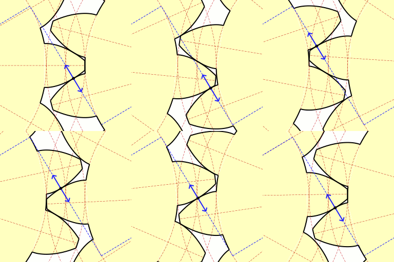
Gear teeth can take a variety of shapes. If you are making a gear you can make the teeth any shape you want. However, one of the more popular/successful shapes is the involute curve. The face of the tooth is bowed out slightly, and the shape of this bow is this curve. Theoretically speaking, this curve is generated by taking a string and winding it around a cylinder. Then take the end of the string and unwind it while keeping tension on it. The path the end of the string takes is an involute curve.
Common diagrams of gear trains often include the "pitch circle", and if you look at these diagrams you will see that the pitch circle runs mid-way through the face of the teeth, half way between the root of the tooth and the tip. The pitch circles of two meshed gears will be tangent to each other. If you take this diagram as gospel you might think that force is transmitted between the gears along this line, i.e. tangent to the pitch circle. This is wrong.
 Here is a fine gif animation by Claudio Rocchini that shows what's going on. Notice the the blue line running at a diagonal from the upper left to the lower right. This line is tangent to the base circle of both gears. Note the short, solid blue, double ended arrow sliding along this line. The center point of the arrow coincides with the contact point between two teeth. This dotted line is like the string being unwound from one gear. As the gear on the left hand side of the picture turns, it is paying out string along this dotted blue line. The gear on the right hand side of the picture, the driven gear, is taking up this imaginary string. If the gears were not moving, and we were unwinding the string from one, the end of the string would coincide with the face of the gear tooth. It would form the "involute curve". Slick.
Anyway, I had been messing around with numbers and drawings, and I wonder if I can get a Google Spreadsheet to plot an involute curve for me. I mean it does charts for all kinds of numbers, it should be able to do this. So mucked about for a day or two and didn't really get any results I liked. I finally decided this was another intractable equation. Someone with a better knowledge of trigonometry might be able to come up with a better equation, I had spent enough time on it, so I decided I would use brute force. I set up a program to use root finder to find the angle that coincides with a specific X coordinate, then used that angle to compute the Y value. Print out the X and Y coordinates (from X = 1 to X = PI/2) and import that file into a Google spreadsheet. Point and click and presto, the graph.
Update September 2016 replaced missing pictures.


2 comments:
Now THAT is a great animation, explaining a lot in one simple video! Is there also one of a worm gear?
It is perhaps also worth pointing out that the numbers of teeth on the gears should be co-prime in order to minimise the wear on the teeth faces.
For all you gearheads, this site may interest you:
http://kmoddl.library.cornell.edu/index.php
Once upon a time I got ahold of a Boston Gear catalog, and I thought cool! I can build my own transmission out of gears I can buy off the shelf. Not so fast, beanball. Seems those massive five inch diameter gears that transmit 300 horsepower in your automotive transmission are not the same animal as the massive five inch diameter gears you find in the Boston Gear catalog. Those gears are rated at a fraction of a horsepower. Funny how much technology mass production can squeeze into a little tiny space.
Post a Comment